Since entering commercial service on the Airbus A320neo in August 2016, the CFM LEAP engine family has become the dominant powerplant for the world’s narrowbody fleet. By 2025, LEAP series deliveries had surpassed 4,000 aircraft, making it the fastest production ramp-up in commercial aviation history. The LEAP-1A powers the Airbus A320neo/A321neo/A319neo family; the LEAP-1B is the exclusive engine for the Boeing 737 MAX; and the LEAP-1C is purpose-built for the COMAC C919.
That commercial success, however, comes with a set of maintenance challenges unique to the LEAP generation. The engine’s advanced materials and operating temperatures — including ceramic matrix composite (CMC) high-pressure turbine (HPT) shrouds, additively manufactured fuel nozzles, and woven composite fan blades — introduced durability issues that were not fully replicated during pre-service testing. Early in-service data revealed premature HPT blade wear in harsh operating environments (high heat, sand ingestion, contaminated air), resulting in Time-on-Wing (TOW) below initial projections and compressed maintenance intervals.
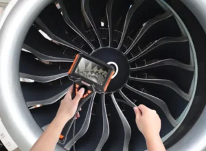
Against this backdrop, video borescope inspection (BSI) has become the single most important tool for on-wing health monitoring of LEAP engines. Unlike a shop visit, a borescope inspection allows technicians to visually assess hot-section components — combustion chamber, HPT blades, CMC shrouds, low-pressure turbine (LPT) — without engine removal, enabling early defect detection, evidence-based disposition, and TOW extension.
This guide provides a systematic overview of CFM LEAP borescope inspection: engine architecture, access port locations, inspection priorities at each module, damage morphology interpretation, and equipment requirements. It is intended for MRO engineers, NDT technicians, and airline technical operations personnel responsible for LEAP fleet airworthiness.

CFM LEAP Engine Architecture Overview
Three Variants at a Glance
Understanding the differences between the three sub-variants is a prerequisite for conducting targeted borescope inspections. The table below summarises the key distinctions:
| Parameter | LEAP-1A | LEAP-1B | LEAP-1C |
|---|---|---|---|
| Aircraft application | Airbus A319/A320/A321neo | Boeing 737 MAX 7/8/9/10 | COMAC C919 |
| Thrust range | ~24,500 – 32,900 lbf | ~23,000 – 30,000 lbf | ~27,980 – 30,000 lbf |
| Inlet configuration | Underwing pod, dual inlet | Single inlet (CFM56-style nacelle) | Dual inlet (similar to -1A) |
| HPT shroud material | CMC (ceramic matrix composite) | CMC (ceramic matrix composite) | CMC (ceramic matrix composite) |
| Primary BSI focus areas | HPT blades, CMC shroud, combustor | HPT blades, combustor, LPT | Same as -1A; also reverser system |
Key Technology Features and Their Maintenance Implications
Woven composite fan blades: LEAP fan blades use three-dimensionally woven carbon fibre composite construction, saving approximately 15% in weight compared to the aluminium blades on CFM56 engines. During borescope inspections, the priority is detecting foreign object damage (FOD) at the leading edge and any indication of inter-ply delamination.
CMC high-pressure turbine shroud: The CMC shroud is the most demanding maintenance challenge on the LEAP engine. Although CMC offers outstanding thermal resistance, the environmental barrier coating (EBC) that protects the CMC substrate is susceptible to spallation in high-temperature combustion gas combined with particulate ingestion. EBC loss increases blade-tip clearance, degrades EGT margin, and can precipitate downstream damage.
Stage 1 HPT rotor blade: Operational experience with the LEAP fleet has shown that Stage 1 HPT blades are prone to premature leading-edge oxidation and airfoil cracking in demanding environments — particularly in the Middle East and South Asia. GE Aerospace and CFM completed certification of an improved HPT durability hardware kit for the LEAP-1A in December 2024, and installation is progressively underway across the fleet.
Additively manufactured fuel nozzles: LEAP fuel nozzles are produced as a single-piece printed component that consolidates 18 previously discrete parts. The integrated design improves durability but combustor borescope inspections should still assess nozzle outlets for coking build-up.
Borescope Access Ports and Inspection Scope
Primary Borescope Access Ports
LEAP engines are fitted with dedicated borescope ports spanning the full hot section, from the high-pressure compressor (HPC) through to the LPT. The table below maps each major access location to the corresponding inspection targets and typical defect types:
| Module | Port location | Inspection targets | Typical defect types |
|---|---|---|---|
| High-Pressure Compressor (HPC) | HPC case stage ports | Rotor and stator blades, each stage | FOD, corrosion, tip rub, erosion |
| Combustion Chamber | Combustor outer case ports | Liner panels, fuel nozzle outlets, igniters | Hot-streak burn-through, cracking, coking, distortion |
| Stage 1 HPT | HPT case Stage 1 ports | S1 rotor blades, S1 nozzle guide vanes, CMC shroud segments | Blade cracking, leading-edge oxidation, EBC spallation |
| Stage 2 HPT | HPT case Stage 2 ports | S2 rotor blades, S2 nozzle guide vanes | Impact damage, trailing-edge cracking, material oxidation |
| Low-Pressure Turbine (LPT) | LPT case ports | LPT rotor and stator blades, all stages | Upstream debris impact, nicks/gouges, tip curl, bending |
Events That Trigger a LEAP Borescope Inspection
In accordance with CFM maintenance documentation and established MRO practice, a borescope inspection should be initiated promptly — or immediately — following any of the events listed below:
- Significant or progressive deterioration of EGT margin
- N1 or N2 vibration levels elevated beyond reference limits
- Confirmed or suspected FOD ingestion event
- Engine over-temperature event — hot-section assessment required
- In-flight shutdown (IFSD) — ground BSI before return to service
- Scheduled BSI at A-, C- or D-check intervals per the maintenance programme
- Pre-purchase or end-of-lease asset condition inspection
- Engine performance recovery wash — pre-wash and post-wash comparison
- Bird strike — compressor and combustor evaluation
Key Inspection Areas in Detail
Stage 1 HPT Rotor Blades
The Stage 1 HPT rotor blade is the highest-priority inspection target on the LEAP engine — and the component where in-service issues have been most heavily concentrated. Operating at the highest gas temperatures in the engine, these blades are subject to extreme thermal and mechanical loads throughout their service life.
Leading-edge oxidation: Under sustained exposure to high-temperature combustion gas, the thermal barrier coating (TBC) on the blade leading edge progressively spalls. Once the substrate is exposed, oxidation advances rapidly. Under the borescope, leading-edge oxidation presents as darkening, surface roughening or material loss along the leading edge. CFM maintenance documentation requires dimensional evaluation of leading-edge damage depth and length; exceedance of the applicable limit necessitates a planned engine removal.
Tip wear and blade-tip clearance changes: The clearance between the CMC HPT shroud and the rotor blade tips has a direct bearing on engine thermal efficiency and EGT margin. When EBC spallation increases effective tip clearance, EGT margin deteriorates in a measurable trend. BSI should systematically examine the inner surface of the CMC shroud for discrete or widespread areas of coating loss.
Blade cracking: Fatigue cracks typically initiate at stress concentrations in the blade root dovetail or at film-cooling hole edges. In their early stages they are visually subtle — appearing under borescope illumination as fine dark lines. A critical caveat applies: sub-surface or very fine fatigue cracks, particularly at the root dovetail, are frequently below the resolution threshold of any video borescope. Their detection requires fluorescent penetrant inspection (FPI) and eddy-current testing (ET) during a shop visit. Maintenance personnel must understand this inherent limitation and not interpret a clean BSI finding as proof of blade structural integrity.
Cooling hole blockage: LEAP blades incorporate complex internal film-cooling passages. If particulate matter — sand, dust, carbonaceous deposits — accumulates within these passages, localised hot spots develop, accelerating creep and crack initiation, and ultimately risking blade fracture. A water-flow test (WFT) during the shop visit provides the definitive assessment of cooling passage condition; borescope inspection of accessible cooling hole outlets can provide supplementary in-service indicators.
CMC HPT Shroud
The CMC shroud is one of the defining technology differences between LEAP and its CFM56 predecessor, and its assessment represents the most technically demanding aspect of LEAP borescope inspection.
EBC spallation: The environmental barrier coating protects the CMC substrate from degradation in high-temperature water-vapour-rich combustion gas. In high-particulate or high-humidity operating environments, the EBC can develop localised delamination and spallation. Under the borescope this appears as bright-toned patches on the shroud inner surface (bare CMC substrate) or irregular pitting. The distribution, area and depth of EBC loss must be assessed against the accept/reject limits in the engine manual.
CMC matrix cracking: Thermal fatigue cycling can initiate matrix micro-cracks in the CMC substrate. If unchecked, these can propagate to through-thickness cracks and eventually cause material loss. During inspection, the borescope should be traversed methodically around the full circumference of the shroud. Any linear indication requires quantification and manual comparison before a serviceable disposition can be issued.
Shroud segment displacement: The CMC shroud is assembled from a series of arcuate segments. Thermal cycling loads can shift the relative positioning of adjacent segments, causing abnormal gap width at segment interfaces — a finding that is visible under careful borescope examination.
Combustion Chamber
The combustor is another high-frequency BSI target. LEAP uses the TAPS II (Twin Annular Pre-Swirl) combustor, which reduces NOx emissions by approximately 50% relative to CFM56 but operates at higher peak flame temperatures, imposing greater thermal demands on the liner.
Hot streaks and burn-through: Non-uniform combustion can create localised hot zones on the liner panels. Sustained thermal loading strips the thermal barrier coating and, if uncorrected, can burn through the liner substrate. The borescope should scan the full circumference of the liner interior, paying particular attention to the regions immediately downstream of the fuel nozzles.
Fuel nozzle coking: The LEAP single-piece printed fuel nozzle can accumulate carbonaceous deposits at its outlet under certain mission profiles. Coking disrupts fuel atomisation, degrades combustion quality and can influence exhaust emissions. Under the borescope, coking appears as brown or black deposits at the nozzle outlet faces.
Liner cracking: Thermal fatigue produces cracks in the liner wall, particularly near dilution holes and panel attachment features. Crack length must be measured using the borescope’s built-in measurement function and compared directly against the applicable accept/reject limits in the maintenance manual before a disposition is recorded.
LPT Blades
LPT blade damage is predominantly caused by secondary impact from upstream debris — fragments originating in the HPT or combustor. Documented engine events, including multiple CFM56 and LEAP incidents, demonstrate a consistent failure sequence: fracture of a Stage 1 HPT rotor blade generates debris that propagates downstream, causing cascade impact damage across multiple LPT blade rows and culminating in in-flight shutdown.
LPT borescope inspection priorities: leading-edge nicks and gouges from FOD/DOD impact; trailing-edge cracking; nozzle guide vane erosion and oxidation; tip rub marks and blade-tip deformation.
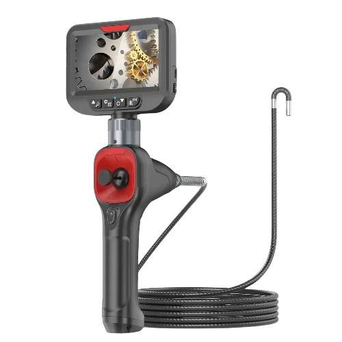
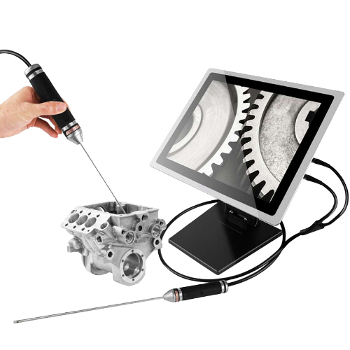
Borescope Equipment Requirements for LEAP Inspections
Probe Diameter and Working Length
LEAP engine access port dimensions differ in some respects from CFM56. Probe selection must match the specific port and inspection target:
- HPT blade inspection: 4 mm or 6 mm diameter probe; minimum working length 1,200 mm
- Combustor inspection: 6 mm probe; working length 1,500 – 2,000 mm
- LPT inspection: 4 – 6 mm probe; working length 1,500 mm or greater
- HPC inspection: 4 mm probe; working length 1,000 – 1,500 mm
Image Quality and Measurement Capability
The damage morphology associated with LEAP’s advanced materials — CMC, TBC coatings — is often more subtle than equivalent defects on CFM56 hardware. Higher imaging performance is therefore required:
- Sensor resolution: 1080p minimum; high-quality still image capture and HD video recording essential for documentation and post-inspection review
- Built-in measurement: point-to-point, area and depth measurement functions are necessary to quantify crack length, pit dimensions and coating loss area for comparison against manual limits
- Full-articulation: 360-degree all-direction steering capability to achieve coverage of all blade surfaces and the full circumference of the annular combustor
- Light output: high-intensity LED illumination is important when inspecting CMC surfaces, whose optical properties differ markedly from metallic hardware — adequate brightness helps resolve the boundaries of fine EBC spallation
AI-Assisted Inspection: An Emerging Standard
GE Aerospace and Waygate Technologies have jointly developed and commercially released an AI-powered Blade Inspection Tool (BIT) for LEAP and GEnx engines. The system applies machine-learning algorithms to borescope imagery in real time, raising defect detection rates by approximately 34% while reducing false alerts by over 13% versus the previous generation model. For operators and MROs managing large LEAP fleets, AI-assisted BSI is no longer a future concept — it is an actively deployed capability that reduces inspector fatigue, shortens turnaround time, and generates a structured digital record of each inspection.
Standard On-Wing Borescope Inspection Procedure
Pre-Inspection Preparation
- Confirm the applicable AMM or CMM revision for the specific engine variant (LEAP-1A, -1B or -1C). Never apply limits from one sub-variant to another.
- Review recent engine health monitoring data: EGT margin trend, vibration history, ACARS engine reports. Identify modules that should receive heightened scrutiny.
- Verify cold soak is complete. A minimum of two hours after engine shutdown is typically required before probe insertion to prevent thermal damage to the instrument and risk of injury to personnel.
- Carry out equipment serviceability checks: probe cleanliness, objective lens condition, measurement function calibration verification.
- Confirm safety precautions: rotor lock installed (windmilling prevention), inlet guard in place, work area secured.
Inspection Execution
Systematic coverage: Inspections must proceed in the sequence prescribed by the maintenance manual. HPT blade assessment requires an external turning tool to rotate the rotor incrementally, ensuring that each blade’s pressure face, suction face, leading edge, trailing edge and platform are all brought into the field of view.
Defect recording: On encountering any suspect indication, halt the probe, capture multiple high-resolution still images from different angles, record video, and document all available measurements. The written record should include: blade position identifier (clock position, e.g. 2 o’clock, blade 3 from reference), defect type, maximum dimensions (length/width/depth) and distance from the nearest fixed reference feature.
Manual comparison: Every finding must be individually compared against the accept/reject criteria in the applicable AMM or CMM before a disposition is reached. LEAP maintenance documentation contains explicit quantitative limits for each recognised defect mode on HPT blades and combustor hardware. Disposition must never be based on inspector experience alone.
Inspection Reporting and Data Archiving
A well-structured borescope inspection report is a critical asset in LEAP engine life-cycle management. Each report should contain, at minimum:
- Engine serial number (ESN), total time since new (TSN), total cycles since new (CSN)
- Inspection date, station, inspector identity and qualification reference
- Borescope equipment model and current calibration status
- Image and video files organised by module and blade position
- Detailed description of all findings, with measurement data and comparison to applicable limits
- Overall disposition: Serviceable / Monitor at Next BSI / Plan Removal / Immediate Removal
Key Differences Between LEAP and CFM56 Borescope Inspections
Many MRO engineers have accumulated extensive CFM56 borescope experience. The transition to LEAP demands awareness of the following material differences:
| Area | CFM56 | CFM LEAP |
|---|---|---|
| HPT shroud material | Nickel-alloy metal | CMC — inspection must identify EBC spallation on a non-metallic substrate |
| HPT blade cooling complexity | Film cooling; relatively straightforward passage geometry | More complex internal passages; higher susceptibility to blockage by particulate ingestion |
| Combustor architecture | Conventional single-annular combustor | TAPS II twin-annular pre-swirl combustor; higher peak flame temperature |
| Principal inspection challenge | HPT blade fatigue cracking; missed cracks at root dovetail | CMC shroud EBC spallation assessment; HPT blade early wear quantification |
| AI inspection tool availability | Traditional visual inspection | GE Aerospace / Waygate AI Blade Inspection Tool (BIT) now commercially deployed |
| TOW performance | Mature fleet; relatively predictable TOW | Early variants underperformed TOW targets; improved HPT hardware progressively retrofitting the fleet |
Damage Case Studies and Lessons Learned
Cascade Damage from HPT Blade Fracture
Published MRO incident data from Chinese civil aviation operations (source: Non-Destructive Testing, Vol. 35, No. 9, 2013; authors: Dong Wu-Jiang, Guo Ping, Hu Cheng) documents multiple CFM56 HPT blade fracture events with a consistent damage sequence that carries direct lessons for LEAP engine maintenance:
Typical failure sequence: A Stage 1 HPT rotor blade fractures — typically at one-third span or at the root — and the released fragment is carried downstream at high velocity, shearing through an entire stage of LPT rotor blades, damaging nozzle guide vanes, and causing in-flight shutdown.
The inherent limitation of borescope inspection: These events also exposed a fundamental constraint of on-wing BSI. Early-stage fatigue cracks — particularly at the root dovetail — are typically undetectable by borescope and can only be reliably found during shop visit NDT using FPI and ET. A serviceable borescope finding does not confirm blade structural integrity. On-wing BSI and shop-visit NDT are complementary processes; neither substitutes for the other.
Implication for LEAP maintenance: Although LEAP HPT blades incorporate more advanced materials and cooling, the underlying fatigue damage mechanisms remain. MRO engineers should correlate EGT margin trends with borescope findings rather than relying on a single inspection snapshot. An engine showing progressive EGT degradation warrants an elevated disposition even in the absence of visible blade distress.
Sand and Dust Ingestion: The LEAP Fleet Experience
In high-particulate operating environments — the Middle East, South Asia, North Africa — the LEAP fleet has experienced significant HPT blade cooling passage blockage. Sand accumulation inside the blade cavities can completely obstruct film-cooling holes, creating localised hot spots that accelerate creep and crack initiation and ultimately precipitate premature blade fracture.
CFM’s response was the HPT Durability Kit — an improved Stage 1 rotor blade and nozzle guide vane package specifically engineered for harsh-environment operations, FAA-certified in December 2024 and progressively entering service. Operators in affected regions should tighten their BSI intervals and dedicate heightened attention during each inspection to cooling hole condition and leading-edge contamination and oxidation.
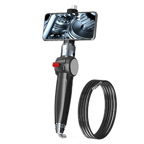
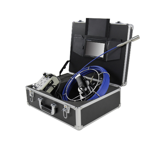
Equipment Selection Guide for LEAP MRO Applications
Borescope performance is a direct determinant of inspection reliability. The following specifications represent the recommended baseline for LEAP fleet MRO operations:
- Probe diameter: 4 mm and 6 mm are the primary working diameters, balancing port access with image resolution
- Image quality: 1080p resolution or higher; RAW or high-quality JPEG still image capture to support archiving and post-inspection analysis
- Measurement capability: 3D stereo measurement or shadow measurement — the specific technology is less important than the ability to produce quantified, recordable results for reporting purposes
- Articulation: two-way or four-way steering; maximum tip deflection not less than 180 degrees to navigate combustor and LPT inspection routes
- Light output: high-intensity LED source suited to the low-reflectance optical characteristics of CMC surfaces
- Ingress protection: IP67 or higher — engine bays involve lubricating oil, hydraulic fluid and standing water
- Battery endurance: a minimum of three hours on a single charge to cover a full engine inspection without interruption
- AI integration readiness: as AI-assisted inspection becomes standard practice, selecting a platform that supports third-party AI software integration is a prudent long-term investment
Frequently Asked Questions
Q: How frequently should LEAP engines be borescope inspected?
There is no single universal interval. Frequency is determined by the airline’s engineering department in conjunction with CMM requirements, the operating environment (high-dust/high-temperature regions require tighter intervals) and the engine’s EGT margin trend data. Typical scheduled BSI intervals fall in the 500 – 1,500 flight-hour range, with shorter intervals for harsh-environment fleets. Any EGT anomaly, FOD event or other trigger condition listed above should initiate an unscheduled inspection regardless of flying hours since last BSI.
Q: Must LEAP borescope inspections be performed by certificated personnel?
Yes. Under CCAR-145, EASA Part-145 and FAA AC 65-31, aeroengine borescope inspection is classified as non-destructive testing. Personnel must hold a recognised NDT qualification — typically EN4179/NAS410 Level II or equivalent — or a specific OEM-authorised training certification. All records must be signed by a qualified individual.
Q: Can a borescope inspection detect all blade cracks?
No. As discussed above and illustrated by the case studies, sub-surface or fine fatigue cracks at the blade root dovetail are routinely beyond the detection capability of any video borescope. Their identification requires FPI and ET during a shop visit. The primary value of on-wing BSI lies in monitoring defects that have grown to visible size and tracking their progression over successive inspections — not as a substitute for shop-visit NDT.
Q: What are the main inspection differences between LEAP-1B (737 MAX) and LEAP-1A (A320neo)?
Access port locations, probe insertion angles and the specific accept/reject limits differ between the two variants. The applicable AMM and CMM must be confirmed before beginning any inspection; limits from one variant must never be applied to another. Additionally, the LEAP-1B durability improvement package — the equivalent of the LEAP-1A HPT Durability Kit — is expected to enter service in 2026. Until then, LEAP-1B operators should track the latest CFM Service Bulletins and any applicable Airworthiness Directives for current guidance on HPT blade inspection intervals.
Q: What parts of the LEAP engine can an industrial video borescope access?
An industrial video borescope can access the HPC multi-stage blade path, the combustor liner and fuel nozzles, the Stage 1 and Stage 2 HPT blades and CMC shroud, and the LPT blade stages. It is not applicable to cross-section metallographic analysis or material property testing, and it cannot detect closed sub-surface cracks — both of those requirements must be addressed by shop-visit NDT methods.
Conclusion
The CFM LEAP engine family is now the most widely deployed narrowbody powerplant in the world, and its MRO demand is set to grow significantly over the coming decade as the fleet continues to mature and the operational cycles accumulate. Borescope inspection sits at the centre of on-wing health management for LEAP, and its importance will only increase as in-service hours build up across the global fleet.
Meeting the demands of LEAP borescope inspection requires moving beyond CFM56 practices. The shift to CMC shroud assessment, the quantification of HPT blade early wear, and the structured documentation requirements of modern airworthiness management all place a premium on the skills of NDT technicians and the performance of their equipment. The emergence of AI-assisted inspection tools — already commercially deployed for LEAP — signals a structural change in how high-volume blade inspections will be conducted in the years ahead.
Selecting the right industrial video borescope is therefore not simply a procurement decision; it is a technical commitment that directly influences inspection reliability, fleet availability and ultimately airworthiness. Probe diameter, image resolution, measurement accuracy and AI platform compatibility should all be weighed carefully against the specific requirements of the LEAP inspection programme.